UNOBAT 78+ BATTEN SPORTS FLOOR
SPECIFIER'S AND INSTALLATION INSTRUCTIONS
D 18.1
D 18.1
1. SPECIFIER'S INSTRUCTIONS
INFORMATION
UNOBAT 78+ BATTEN SYSTEM
|
D 1.0 |
General information |
|
D 18.1 |
Specifier's and |
Table 1
1.1 SYSTEM SPECIFICATION
The Junckers Unobat 78+ sports floor system is based on Junckers 22 mm solid hardwood floorboards fixed to an undercarriage system consisting of single layer of engineered battens and wedges with integrated shock pads.
The UnoBat 78+ wedges allow quick and easy levelling of uneven subfloors to provide a flat playing surface. The levelling process does not require glue, nails or specialist tools.
Packing blocks in a selection of thicknesses are available to extend the height of the system. The blocks are clipped to the base of the wedges and are available in 20 mm, 30 mm, 40 mm and 50 mm thicknesses. A maximum of two blocks can be used, per wedge.
Batten distance: Choose between c/c 336 and 411 mm centres. The batten spacing is determined on the basis of loading and strength requirements. For floors in dedicated basketball halls 336 mm batten centres are recommended.
Battens along walls: To avoid deflection of the floor along walls, 39 mm x 40 mm gable battens used as starters are included in the system. Gable battens are supported by height adjustable Junckers DuoWedges.
Construction height: min. 78 mm and max. 205 mm.
Performance: The floor system is an area elastic sports floor with a high level of shock absorption and resilience. Very suitable for multi purpose sports halls, fitness suites, dance and drama studios and squash courts. Junckers Unobat 78+ is tested, certified and approved according to the European standard EN 14904, Class A4 and FIBA Level 1.
Step sound reduction:
22 mm Junckers solid hardwood floorboards and UnoBat 78+ battens: 19 dB.
For general information and practical guidelines on acoustics in floor constructions, see Junckers technical data sheet E 5.0.
Please read all information in this document and note further related documents are shown in Table 1. If you have any questions, please contact Junckers Technical Service.
1.2 SYSTEM COMPONENTS - UNOBAT 78+ BATTEN SYSTEM
-
Junckers 2-strip solid hardwood floorboards
Thickness x width x length
22 x 129 x 3700 mm
For wood Species, grade and surface finish,
see data sheet B 2.0 -
Junckers J-Nails (Machine nail)
2,2 x 45 mm special J-nails with a high shear - and pull-out strength. -
Laminated battens
27 x 60 x 3360 mm
Gable battens 39 x 40 x 3600 mm
Batten distance:
c/c 336,4 mm (336)
c/c 411,1 mm (411)
Unobat 78+ battens are made of spruce and/or pine, with a moisture content of 8-10 %. -
Packings
Adjustable Unobat 78+ wedges. -
SylvaThene moisture barrier
Min. 0,20 mm PE-foil. -
Expansion gaps at walls
1.5 mm per metre width on each side and 1 mm per metre length at each end, but both min. 15 mm. Expansion gaps are also required at all fixed points, e.g. columns, pipes, door thresholds etc. Gaps at walls can be covered with Junckers ventilated combi sports skirting.
Fig. 1

1.3 LOAD BEARING STRENGTH
The System is designed to bear common loads from sports and similar actitivities. In order to reduce the risk of damage, a stop mechanism is built into the floor system, which is activated at high loads. The stop mechanism has no function during normal sports use.
Load Bearing capacity; Point Loads
The UnoBat 78+ batten system is tested and approved for the maximum point loads shown below, for 336 mm or 411 mm batten centres.
Table 2 shows the maximum point load bearing capacity for the batten system's recommended batten distances for different types of point load.
|
Table 2 |
|
|
Batten distance c/c 336 mm: |
Batten distance c/c 411 mm: |
|
Diameter 25 mm: 4,5 kN (approx. 450 kg) |
Diameter 25 mm: 4,0 kN (approx. 400 kg) |
|
100x100 mm: 6,0 kN (ca. 600 kg) |
100x100 mm: 5,5 kN (ca. 550 kg) |
Table 3 shows use categories which apply to the floor system in relation to the load classes in EN 1991-1-1, corresponding to load bearing requierements and the floor having acceptable stiffness. The wheel loading capacity of the system is also shown.
For further definition of load classes and types, see General Information Junckers Sports Floors D 1.0 - stiffness and loadbearing strength.
|
Table 3 |
Loading types |
|
|
Loading category |
Area and Point load |
Wheel load |
|
C4: Assembly halls for physical activity, e.g. gyms/theatres |
Approved* |
Approved** |
|
C5: Assembly halls which can be crowded, e.g. sports halls incl. stands |
Approved* |
Approved** |
* Point load area min. 200 x 200 mm / ** Wheel loads, see D 1.0 - Table 2
1.4 FLATNESS OF THE SUBFLOOR
After installation the top surface of the battens may deviate a maximum of 2 mm from flat level under a 1.5 m straight edge (UK: 3 mm under a 2 m straight edge), both parallel and perpendicular to the floorboard direction.
Fig. 2
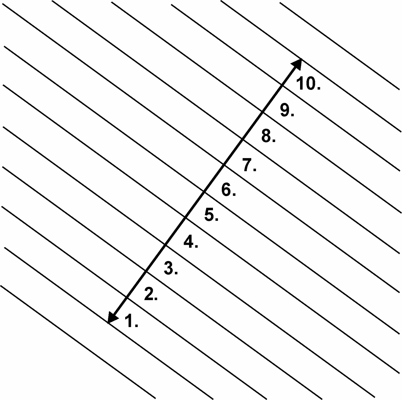
1.5 THE 10-BOARD RULE
In order to minimise stress or gaps in the floor due to fluctuations in the climatic conditions within the building, floorboards must be laid according to a 10‑board rule.
The 10-board measurement is the measurement of 10-board widths, including expansion gaps, at the time of installation. This indicates the measurement across 10 floorboards when laid. This must be checked continuously during the installation process and prior to hand over. See Fig. 2.
To achieve a consistent 10-board measurement (10 BM), it is recommended to use Junckers temporary spacers during installation of the floor. Spacers are supplied in a range of sizes to suit the expected relative humidity of the room.
Fig. 3
The 10-board measurement is chosen on the basis of the expected maximum relative humidity in the building when in use throughout the year, see Fig. 3
The graph in Fig. 3 illustrates the 10-board rule in relation to the relative air humidity for 129 mm wide floorboards. E.g. an expected relative humidity of max. 65 % RH will normally require a 10-board measurement of approx. 1294 mm.
The outer limits of the 10-board measurement, which also depend on the floor size, are marked with dotted lines.
The size of the floor, as well as its location, i.e. ground floor or upper floor, may also have influence on the choice of the 10-board measurement.
For further information please contact Junckers technical service department.
Fig. 4

1.6 THERMAL INSULATION AND PIPES IN THE SUBFLOOR
The batten system provides a good opportunity to include thermal insulation.
There must be sufficient ventilation between the underside of the floorboards and the insulation. This is to prevent fungal attack beneath the floorboards.
All central heating, cold and hot‑water pipes under floors must be carefully insulated using at least 20 mm thick mineral wool or similar.
It must be ensured that there is sufficient space between underside of the floorboard or batten and the pipe insulation so as not to restrict vertical deflection of the floor when in use, see Fig. 4.
1.7 MOISTURE PROTECTION
Concrete Subfloors
The residual moisture contained in the concrete or screed must not exceed 90 % RH.
(In UK: concrete moisture max. 75 % RH acc. to BS 8201)
At ground level and upper floor levels, protection against moisture both from within the building and from the ground is required.
A moisture barrier must be provided, comprising, 0.20 mm PE membrane or 1000 gauge polythene, e.g. Junckers SylvaThene moisture barrier, directly on the concrete subfloor before laying out the battens, see Fig. 4 (dotted line).
Wooden Subfloors
For renovation projects where new floor systems are laid on existing wooden subfloors, it must be ensured that the entire structure has been designed to the correct specifications in relation to protection from moisture.
When over-laying existing wooden sports floors, no additional moisture protection must be applied on top of the existing sports floor, as this may result in moisture issues or rot in the subconstruction.
1.8 VENTILATION OF THE SUBFLOOR
For the UK and Ireland
It is not usually necessary to ventilate the floor void within a Junckers battened floor system. In cases where a ventilated DPM is used it will usually be necessary to use a ventilated skirting such as Junckers Combi Skirting, where the optional ventilation spacers must be specified.
General Requirements other than the UK/ Ireland
In some countries, local building regulations stipulate that skirtings with ventilation slots must be used in sports halls, to ensure adequate ventilation of the substructure. Moreover, to minimize the consequences of environmental fluctuations in the building as much as possible, the same climate should be maintained both above and below the floor surface.
The expected relative humidity range will usually be complied with through natural ventilation via the aforementioned ventilation slots. By natural ventilation we mean the air flow will be as a consequence of movement of the floor surface during normal sports activities.
In all circumstances it is important that the ventilation slots at the walls be retained and that the moisture-protection instructions are observed, see Moisture protection.
1.9 NET CONSUMPTION OF MATERIALS
Net consumption for 1000 m² (Length x width = 40 x 25 m) UnoBat 78+ batten system:
Floorboards: 1000 m² + approx. 2 % waste.
J-nails, 2,2 x 45 mm: For c/c 336 mm: 25,000 pcs. For c/c 411 mm: 20,000 pcs.
UnoBat 78+ battens: For c/c 336 mm: 2950 rnm + 2 % waste. For c/c 411 mm: 2450 rnm + 2 % waste
Gable battens: 50 rm
Adjustable UnoBat 78+ wedges:
c/c 336 mm: 7100 pcs / 7.1 pcs/m²
c/c 411 mm: 5800 pcs. / 5.8 pcs/m²
Duowedges: 160 pcs. (c/c 336/411 mm)
Loose tongues: Approx. 70 pcs. (5 bags)
Junckers SylvaThene moisture barrier: Min. 0,20 mm PE-foil: 1100 m² overlap included.
Junckers SylvaFix header joint adhesive: 3 bottles of 0,75 litre.
2. INSTALLATION INSTRUCTIONS
WHEN TO START INSTALLATION
The building must be weather tight. The heating system must be installed and tested, and during the heating season there should be a constant heat supply.
Cast concrete elements, including casting of sockets for fixtures and fittings, screeding and other wet trades which can contribute moisture to the building, e.g. priming of paintwork, must also be completed.
The relative humidity in the building must be between 35-65 % RH (UK) and the temperature approx. 16-20 °C.
The residual moisture contained in the concrete or screed must not exceed 90 % RH. (UK: 75 % acc. To BS 8201). In wooden based sub floors the moisture content should not exceed 12 %.
Solid floorboards should always be laid immediately after arrival at the building. The wrapping of the floorboards must not be removed until just prior to laying the floor, i.e. no acclimatising of the boards on site must take place.

2.1 MOISTURE BARRIER
On concrete or screed subfloors a moisture barrier of min. 0.20 mm PE membrane is laid, e.g. Junckers SylvaThene moisture barrier.
The moisture barrier is laid with an overlap of 200 mm at all joints, continuing up walls, etc.
The moisture barrier must be taped at all lap joints.
2.2 EXPANSION GAPS AT WALLS AND FIXED POINTS
The minimum expansion gap at walls and all fixed points must be 15 mm and calculated at 1.5 mm per m width at each side and 1 mm per length at each end of the floor in order to allow for seasonal movement of the boards.
The gap between wall and floor can be covered with Junckers Combi sports skirting.

2.3 SUBCONSTRUCTION, BATTEN CENTRES 411 MM
The battens are laid parallel to the shortest side of the room to ensure that the boards are laid parallel to the longest side of the room.
Before laying out the battens, the enclosed UnoBat 78+ wedges are clipped on to the battens, see section 2.5.
The first and last rows of battens are laid with a distance of 100 mm from the wall to the centre of the batten (Note that these are special battens called Gable Battens, without shock pads, and marked with red tape on the bundles).
The second batten row is centred at 341 mm to the first batten row (example, based upon 30 mm expansion gaps).
All other batten rows are centred at 411.1 mm (board length 3700 mm, spanning 9 battens) by using the Spacing Battens (A) marked with black tape on the bundles).
Wedges on battens are staggered in a line 210 mm from the adjacent row. Batten end joints should not be in line but must be staggered min. 600 mm from the neighbouring row. Use staples to keep batten end joints together. Max staple length: 25 mm.

2.4 SUBCONSTRUCTION, BATTEN CENTRES 336 MM
Except for the batten centres, the battens are laid according to the instructions in section 2.3.
The first and last rows of battens are laid with a distance of 100 mm from the wall to the centre of the batten.
The second batten row is centred at 266 mm to the first batten row row (example based upon 30 mm expansion gaps).
All other batten rows are centred at 336.4 mm (board length 3700 mm, spanning 11 battens) by using the Spacing Battens (A) marked with black tape on the bundles).

2.5 LEVELLING THE SUBCONSTRUCTION
Battens (1) are levelled using the UnoBat 78+ wedges (2).
Gable battens (3) are levelled using DuoWedges (4).
Extra wedges are fitted at each end of the batten rows, where the last batten is fitted by the wall. The wedges by the wall must be fixed to the battens with screws. This way the wedges are solid packed to avoid unnecessary deflection of the floor along the walls. UnoBat 78+ wedges are snapped onto the underside of the battens in the positions where marked with red lines. Each batten requires 8 no. wedges.
The substructure can now easily be levelled by using the wedges to achieve the required flatness. The wedges can be used either alone or in combination with bases (available in 20, 30, 40 and 50 mm thickness), to achieve the required floor height. Use no more than two bases under each wedge.

2.6 BATTENS AT NET POSTS, PIPES ETC.
Place additional battens and wedges at net posts, pipes, etc.
For details of expansion allowances at walls, net posts, pipes, etc, see section 2.2.
Squash:
If the floor is used in a squash court, permanent spacing blocks at 500 mm centres are attached between the first batten row and the front wall.

2.7 LAYING FLOORBOARDS
If the floor is more than 12 m wide the installation must begin in the middle of the sports halls. Use one of the following two methods:
- The two centre floorboards are joined with a loose tongue which must be glued to one of the floorboards along the full length of the hall.
- Use Junckers CenterRow boards. These floorboards are constructed with a tongue on both sides.
The floorboards must be laid in a continuous pattern with well-defined distribution of board header joints from row to row of 2 x the batten centres, i.e. 822.2 mm with c/c 411.1 mm, or 4 x the batten centres, i.e. 1345.6 mm with c/c 336.4 mm. In this way all board header joints are supported. The floorboards are secretly nailed, see section 2.10.

2.8 DISTANCE, BOARD HEADER JOINTS - C/C 411 mm
All board header joints must be fully supported and, depending on the batten centres (336 or 411 mm) all boards must be laid in the pattern shown in the drawing.
If 411.1 mm batten centres are used, the distance between board header joints in two consecutive rows must be 2 x 411.1 mm = 822.2 mm, as shown in the drawing.

2.9 DISTANCE, BOARD HEADER JOINTS - C/C 336 MM
If the batten centres are 336.4 mm, the distance between board header joints in two consecutive rows must be 4 x 336.4 mm = 1345.6 mm, as shown in the drawing.

2.10 NAILING
Use Junckers machine J-Nails, 2.2 x 45 mm. The floorboards are secret-nailed at an angle of 45°. Do not nail closer than 50 mm to stave end joints and never at the board end joints.
To avoid creaking, the floorboards must be firmly pushed down onto the battens while they are nailed.
The first and last rows of floorboards installed must be face nailed or screwed and then covered with matching filler.
DURING INSTALLATION, REMEMBER TO MAINTAIN THE CORRECT 10-BOARD MEASUREMENT.

2.11 BUSHINGS
When installing Junckers bushings in the floor the internal diameter of the bushing must exceed the external diameter of the post socket, by at least 40 mm.
At the outermost sides of the floor all bushings are offset towards the middle of the floor in relation to the sockets in the concrete, as illustrated
Bushings must be fitted so as not to restrict vertical deflection and widthways expansion of the floor.

2.12 COMBI SPORTS SKIRTING
Junckers Combi Sports skirting can be used either way up, depending upon the cover required. See illustration opposite.
Combi Skirting may be used either with or without ventilation spacers depending upon whether or not there is a requirement to ventilate the subfloor.
The foot of the skirting must lie flat and be in contact with the floor. End joints may be either butt jointed together or cut as a 45° mitre joint to enhance the visual effect of the joint.
The skirting can be either glued to the walls or screw fixed. Note that if ventilation spacers are used the skirting must be screw fixed.
Do not fix the skirting to the floor and ensure that the skirting is not exerting any downward pressure on the floor.